Swift's X-Ray Telescope (XRT)
For details of XRT data analysis, see the Data Analysis page.
Instrument Description
Swift's X-Ray Telescope (XRT) is designed to measure the fluxes, spectra, and lightcurves of GRBs and afterglows over a wide dynamic range covering more than seven orders of magnitude in flux. The XRT can pinpoint GRBs to 5-arcsec accuracy within 10 seconds of target acquisition for a typical GRB and can study the X-ray counterparts of GRBs beginning 20-70 seconds from burst discovery and continuing for days to weeks. The layout of the XRT is shown in the schematic below; the table after it summarizes the instrument's parameters. Further information on the XRT is given by Burrows et al. (2000) and Hill et al. (2000).
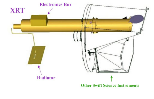
XRT Instrument Parameters
| Property | Description |
|---|---|
| Telescope | JET-X Wolter I |
| Focal Length | 3.5 m |
| Effective Area | 110 cm2@ 1.5 keV |
| Telescope PSF | 18 arcsec HPD @ 1.5 keV |
| Detector | EEV CCD-22, 600 x 600 pixels |
| Detector Operation | Imaging, Timing, and Photon-counting |
| Detection Element | 40 x 40 micron pixels |
| Pixel Scale | 2.36 arcsec/pixel |
| Energy Range | 0.2-10 keV |
| Sensitivity | 8 x 10-14 erg cm-2s-1 in 104 seconds |
Technical Description
The XRT is a focusing X-ray telescope with a 110 cm2 effective area, 23.6 x 23.6 arcmin FOV, 18 arcsec resolution (half-power diameter), and 0.2-10 keV energy range. The XRT uses a grazing incidence Wolter 1 telescope to focus X-rays onto a state-of-the-art CCD.
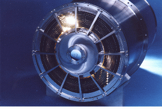
The complete mirror module for the XRT consists of the X-ray mirrors, thermal baffle, a mirror collar, and an electron deflector. The X-ray mirrors (left) are the FM3 units built, qualified and calibrated as flight spares for the JET-X instrument on the Spectrum X-Gamma mission (Citterio et al. 1996; Wells et al. 1992; Wells et al. 1997). To prevent on-orbit degradation of the mirror module's performance, it is be maintained at 20° ± 5° C, with gradients of <1° C by an actively controlled thermal baffle (purple, in schematic below) similar to the one used for JET-X. A composite telescope tube holds the focal plane camera (red), containing a single CCD-22 detector. The CCD-22 detector, designed for the EPIC MOS instruments on the XMM-Newton mission, is a three-phase frame-transfer device, using high resistivity silicon and an open-electrode structure (Holland et al. 1996) to achieve a useful bandpass of 0.2-10 keV (Short, Keay, & Turner 1998).

The CCD consists of an image area with 600 x 602 pixels (40 x 40 microns) and a storage region of 600 x 602 pixels (39 x 12 microns). The FWHM energy resolution of the CCDs decreases from ∼190 eV at 10 keV to ∼50 eV at 0.1 keV, where below ∼0.5 keV the effects of charge trapping and loss to surface states become significant. A special &suot;open-gate" electrode structure gives the CCD-22 excellent low energy quantum efficiency (QE) while high resistivity silicon provides a depletion depth of 30 to 35 microns to give good QE at high energies. The detectors operate at approximately -100° C to ensure low dark current and to reduce the CCD's sensitivity to irradiation by protons (which can create electron traps that ultimately affect the detector's spectroscopy).
Operation and Control
The XRT supports two readout modes to enable it to cover the dynamic range and rapid variability expected from GRB afterglows, and autonomously determines which readout mode to use. Imaging Mode produces an integrated image measuring the total energy deposited per pixel and does not permit spectroscopy, so will only be used to position bright sources. Photon-counting Mode uses sub-array windows to permit full spectral and spatial information to be obtained for source fluxes ranging from the XRT sensitivity limit of 2 x 10-14 to 9 x 10⁻¹⁰ erg cm-2 s-1.
Instrument Performance
Position
The mirror point spread function has a 15 arcsec half-energy width, and, given sufficient photons, the centroid of a point source image can be determined to sub-arcsec accuracy in detector coordinates. Based on BeppoSAX and RXTE observations, it is expected that a typical X-ray afterglow will have a flux of 0.5-5 Crabs in the 0.2-10 keV band immediately after the burst. This flux should allow the XRT to obtain source positions to better than 1 arcsec in detector coordinates, which will increase to ∼5 arcsec when projected back into the sky due to alignment uncertainty between the star tracker and the XRT.
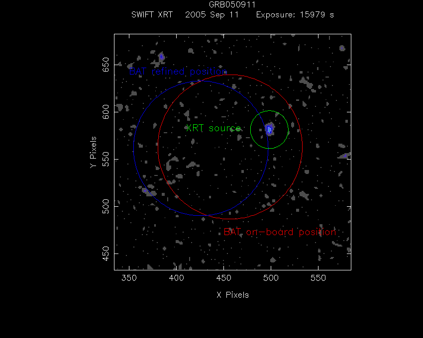
Below is an XRT image of GRB 050911 comparing the BAT error circle with the X-ray afterglow. The brightest source in the XRT field of view during the initial observation will almost always be the GRB counterpart, and so this source's position can be sent to the ground-based observers for rapid followup with narrow FOV instruments, such as spectrographs.
Spectra
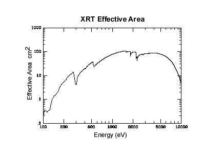
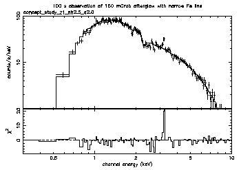
The XRT resolution at launch was ∼140 eV at 6 keV, with spectra similar to that shown below. Fe emission lines, if detected, can provide a redshift measurement accurate to about 10%. The resolution will degrade during the mission, but will remain above 300 eV at the end of the mission life for a worst-case environment. Photometric accuracy is be good to 10% or better for source fluxes from the XRT's sensitivity limit of 2 x 10-14 erg cm-2 s-1 to ∼8 x 10⁻⁷ erg cm-2 s-1 (about 2 times brighter than the brightest X-ray burst observed to date).
Sample Spectrum
Further Information
Further detail on the development and performance of the XRT is available from the instrument team site:
References
- Burrows, D. N., et al., 2000, Proc. SPIE, 4140, 64
- Citterio, O. et al., 1996, Proc. SPIE, 2805, 56
- Hill, J. E. et al., 2000, Proc. SPIE, 4140, 87
- Holland, A. D., Turner, M. J., Abbey, A. F., & Pool, P. J., 1996, Proc. SPIE, 2808, 414
- Short, A. D., Keay, A., & Turner, M. J., 1998, Proc. SPIE, 3445, 13
- Wells, A., et al., 1992, Proc. SPIE, 1546, 205
- Wells, A., et al., 1997, Proc. SPIE, 3114, 392


