- Calibration Status
- Science Analysis Issues
- 1.00 kHz spurious signal due to energy calibration pulses
- batclean: Incorrect 'Edges' and 'Flight' balancing
- BAT Timing: power spectrum problems with BAT event data
- Analysis: Passive materials distort the off-axis counts/rates
- batfftimage and batmaskwtimg: potentially incorrect derived attitude
- Analysis: Earth and Moon Occultation
- Old Issues
Calibration Status
Overall Spectral Response
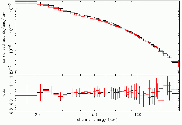
Figure 1. Fit to the Crab using the publicly available corrected response matrix, and including the systematic error vector. The two colors represent on-axis (black) and off-axis 30 degrees (red) long observations.
The pre-launch BAT spectral response file contained significant systematic errors. The response matrix model published with the public Swift software includes extra corrections to force the Crab to fit a canonical model, a power law with photon index 2.15 and normalization of 10.17 ph/cm2/s/keV at 1 keV. Figure 1 shows a fit to the Crab using the corrected response matrix and the estimated systematic error vector.
Corrections to Response
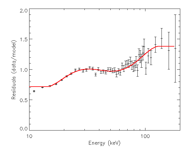
Figure 2. Residuals of a fit to the Crab before "extra corrections" have been applied (points). The smooth line is the form of the extra corrections.
The extra corrections are: (a) addition of empirical absorption which shifts the low energy effective area by ~40% below 25 keV, and (b) a phenomenological adjustment to the effective area over the entire energy range, but which dominated at high energies (~20% for > 100 keV). Figure 2 shows the extent of these corrections in the BAT energy band. While it is believed that these errors are in part due to incorrect modeling of all the passive material in the beam, the exact details are not well understood.
Residual Features

Figure 3. Crab spectrum without applying the systematic error vector, which shows features around 17 and ~30 keV. The different points are at different positions off axis: 0 degrees (red), 30 degrees (green) and 45 degrees (blue).
Features at 17, 27, and 31 keV are still evident in Figure 3. The BAT CdZnTe detectors have K-edges at 27 keV (Cd) and at 31 keV (Te). The response matrix does not yet entirely account for spectral features resulting from these edges, so any such features at these energies should be interpreted with caution. There is also an as-yet unidentified feature at 17 keV.
Flux and Photon Index Systematic Errors
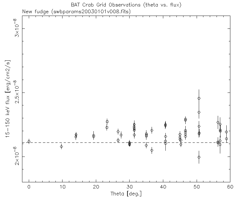
Figure 4. Measured Crab fluxes (14-150 keV) as a function of off-axis angle (theta). The canonical spectrum has a flux of 2.20 x 10⁻⁸ erg/cm2/s in this band.
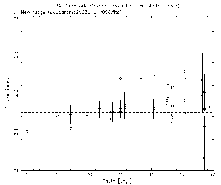
Figure 5. Measured Crab photon indices as a function of off-axis angle. The canonical photon index is 2.15.
Systematic flux and spectral variations as a function of off-axis angle, theta, are shown in Figures 4 and 5 (as of version 008 of the response matrix parameter file). The Crab was observed using a set of 44 grid locations in the BAT FOV (including on-axis, and periodic spacings in tangent plane coordinates all the way out to the 0%-code edge of our field of view). The flux variations are approximately +/-5% peak to peak throughout the field of view. The user must be careful to avoid occultation by the earth/moon for off-axis angles larger than 30 degrees (see the "Occultation" analysis issue). Response matrices were generated for these fits using batdrmgen with the default method=MEAN parameter.
Hard Spectra
The response matrix was generated (a) from a set of ground calibrations with monochromatic lines from radioactive sources and (b) from a forced-adjustment fit to the canonical Crab spectrum (PLI=2.15, Norm=10.17). Given the deviation from ideal discussed above, we recommend caution when fitting sources that have significantly harder spectra than the Crab, in particular GRBs having spectral indices around 1.0 or flatter. While they were to some extent adjusted to match the Crab spectra, the large off-diagonal elements in the response matrix may not be correctly handling the scattering.

Figure 7. The BAT spectrum of GRB 050326. If we fixed the E0 and the beta to the KONUS spectrum, both the alpha and the observed fluence are consistent with the KONUS values.
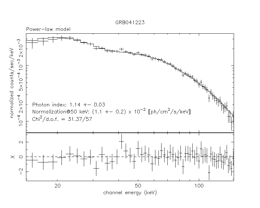
However, the fit to GRB 041223 shows the spectrum to be well fit by a simple power-law model, and the residuals show no sign of any bend in the spectrum (Figure 6). Also, the BAT spectrum for GRB 050326 agrees well with the KONUS spectrum (GCN Circ. #3152) for that burst (Figure 7).
Energy Range
Spectral analysis should be limited to channels between 14 keV and 150 keV. Due to varying threshold levels in individual detectors, channels below 14 keV should not be used for spectral anaylysis. Likewise, channels above 150 keV are unreliable due to a lack of calibration data at those energies.
Effective Area
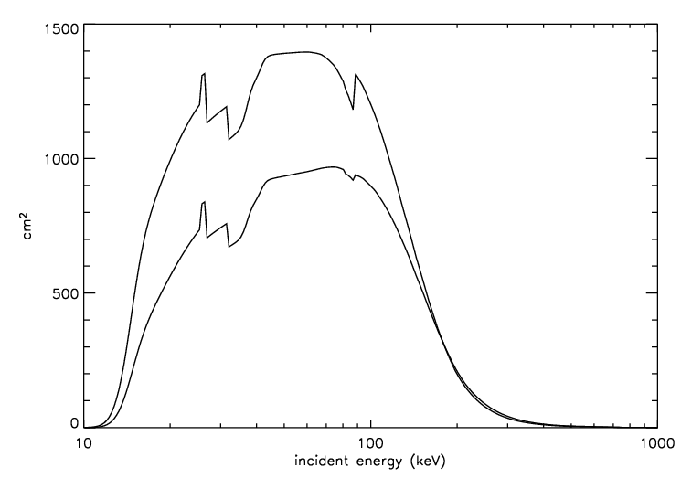
Figure 8 shows the effective area for a source (a) on axis, and (b) a source 45 deg off-axis. This effective area contains the Mask transmission and the 56% efficiency factor due to the cross-correlation technique used for imaging and mask weighted flux determination. Edge features include 25.5 keV (Ag), 26.7 keV (Cd), 31.8 keV (Te), and 88 keV (Pb). The extra silver absorption used to fit the Crab may have produced an unrealistically pronounced silver K edge in the matrix.
Users can also estimate BAT count rates on-line using WebPIMMS.
Applying Systematic Errors
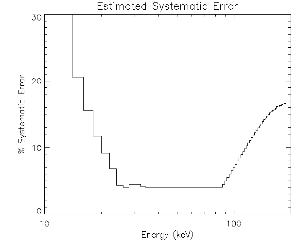
The BAT team has delivered a systematic error vector to be used for all spectral fitting activities. Figure 9 shows this error as a function of energy. The error vector is a FITS file in CALDB containing a fractional systematic error SYS_ERR, and instructions are provided for applying this vector in the Science Analysis Issues section.
This systematic vector was constructed by assuming the correction vector was a constant fraction of the matrix corrections applied, with a minimum of 4% for the entire energy range. The error fraction was determined iteratively, in order to make the parameters derived from Crab on-axis and 30 degrees off-axis agree to within 1-2 sigma.
Energy Scale
Users must use the following tools to obtain the correct energy scale:
bateconvert for event data (i.e. GRB data).
baterebin for binned data (i.e. survey DPH data).
Both of these tools apply a detector-dependent energy shift which accounts for the non-linear behavior of the detector electronics, as well as detector-to-detector offset shifts not currently accounted for by the on-board automatic calibration.
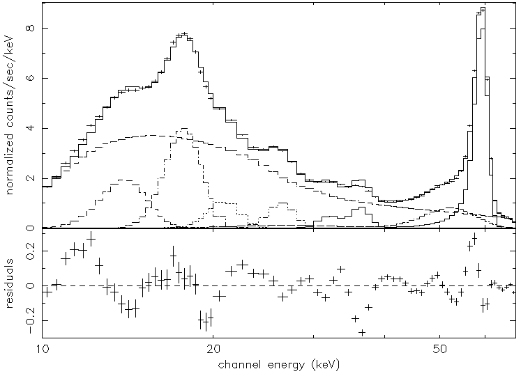
Figure 10. On-board calibration spectrum of the 241Am source. The features include: 241Am lines at 59.5 keV and 26.3 keV (with exponential tail); escape peaks for Cd and Te at 26.7 and 32 keV; L X-ray lines from Np at 14 and 17.75 keV; and a power law representing the sky background.
Figure 10 shows an on-board calibration spectrum with identified lines.
Without the correction, users can expect +/- 2 keV errors (90%, with maximum errors of 10 keV), and increased noise in detector images due to detector-to-detector gain variations.
With correction, users can expect +/- 0.1 keV errors. Figure 11 shows the on-board calibration spectrum after correction. The line centroids are consistent to within 0.1 keV, and the widths are consistent with the broadening derived by ground calibration.
WARNING: The SDC currently does not supply all of the gain/offset files required for energy correction of survey DPHs. Only the first gain/offset map is provided at the start of the observation, when in fact multiple calibrations can occur between snapshots. This will affect long observations the most. However, the gain behavior of the instrument does not appear to be a strong function of time. Using the first gain/offset map will degrade the energy scale, but only slightly.
Please use the newest software and calibration files, since these contain improvements to the energy scale. For event data, it is worthwhile to re-apply the correction since the SDC may not always be using the most recent software or calibration files.
Energy Resolution
As described above, and in Figure 10, the resolution is as expected from modeling of the ground calibration data. For example, the FWHM of the 241Am line at 60 keV is <4 keV.
Position Centroid Uncertainty
BAT positions are derived by generating a sky image using batfftimage and then fitting a point spread function to detected sources using batcelldetect. The BAT-to-spacecraft alignment was analyzed and checked using BAT observations detected in survey mode from approximately 2004-12-15 to 2005-01-15. The alignment data are stored in the BAT teldef and aperture files, and include rotation and focal length adjustments.
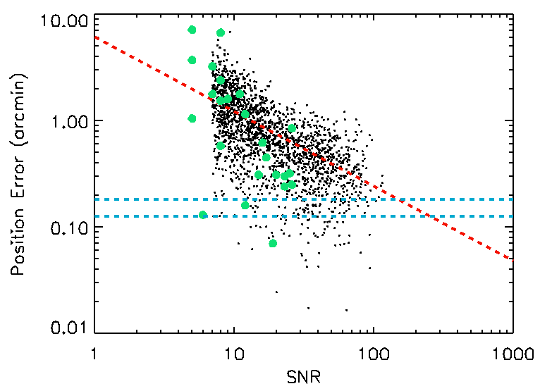
Figure 11. BAT position errors as a function of signal to noise ratio, for known sources. Both ground (black) and flight (green) determined positions are shown. The red line is equation 1 for K=1 (see below). The blue lines indicate approximate error contributions of annual aberration (top) and energy-dependent focal length (bottom), for a typical source 25o off-axis (spectrally hard, power law with photon index -1.0.).
The residuals from the alignment calibration provide information on the centroiding error of the BAT. The residuals in Figure 12 were fit to a power law as a function of signal to noise. The best fit is:
ERR_RAD = K x 6.1 SNR^(-0.7) [arcmin; radius] (equation 1)
where SNR is the signal to noise ratio reported by either batcelldetect or the BAT position message sent by TDRSS. This function is applicable for 6 < SNR < 100, but is poorly tested for partial coding fractions of less than ~25%.
Table 1. BAT centroid uncertainty.
|
Confidence |
K |
10 sigma |
20 sigma |
|
68% |
1.20 |
1.5' |
0.9' |
|
90% |
1.79 |
2.2' |
1.3' |
|
95% |
2.11 |
2.6' |
1.6' |
|
99% |
2.86 |
3.5' |
2.1' |
For specific confidence limits, please use the values for K in Table 1. Also, representative error radii are given for 10 sigma and 20 sigma detections.
Distortion Map
As of Spring 2006, it is now known that there are small scale but systematic image centroid shifts as a function of position in the BAT field of view. Based on 9 months of data from 2004-12-15 to 2005-09-15, the measured positions of known sources were compared to the known positions. The position offsets were preserved in instrument tangent-plane coordinates, and grouped by position in the field of view.
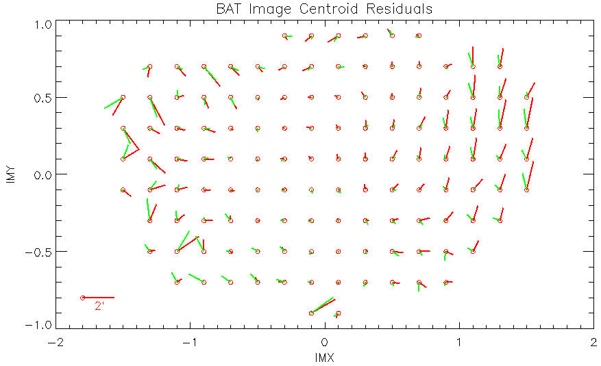
Figure 12. Position offsets as a function of image coordinates. The red lines show the measured position offset, while the green lines show the best possible solution using the aperture+teldef files alone (i.e. the distortion map is required). Coordinates are tangent plane coordinates (IMX and IMY). The vector indicates the offset from the expected (circle) to the measured (non-circle) positions, with the vector scale shown.
Figure 12 shows the resulting measured position offsets. This figure shows that beyond 45 degrees (IMR > 1), there are significant residuals, and within that angle, the residuals are negligible. The maximum residual offset is about 2 arcmin. Note that this effect is commonly only seen for very bright sources, or by averaging several faint source positions together.
The offsets appear to show a systematic but non-regular pattern. The current aperture+teldef model appears to help some, but does not remove the systematic offsets. Thus, a systematic distortion map was developed. This map is a thin-plate spline approximation to the measured offsets, which smooths over the noise in Figure 12, and interpolates between gaps. The resulting spline function is sampled on a regular grid and stored in the swbdistort* file. This file is used by source detection and mask weighting (ray tracing) tasks to produce more accurate fluxes and positions.
Point-Spread Function
|
|
|
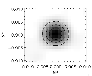
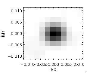
Figure 13. Images of the BAT point spread function for 4-times oversampling (left) and 2-times oversampling (right; the default of batfftimage). The contours indicate 25%, 50% and 75% of unit response.
As shown, BAT point spread function is approximately a gaussian. The measured width of the point spread function is 22.5 arcminutes (FWHM on-axis). In tangent plane coordinates, the PSF shape is very uniform across the BAT field of view; i.e. the FWHM is tan(22.5') = 0.0065 in image coordinates. Figure 13 shows the point spread function for a bright source at two oversampling levels.
As a source moves farther off axis, the transformation between tangent projection and true spherical angles becomes more distorted. The width of the point spread function follows this model:
   FWHM_X = 22.5' / (1 + IMX^2)
   FWHM_Y = 22.5' / (1 + IMY^2)
where IMX and IMY are the tangent plane coordinates. This distortion occurs in celestial coordinates. The PSF shape and width are unchanged in instrument tangent plane coordinates.
Science Analysis Issues
1.00 kHz spurious signal due to energy calibration pulses
Task: Timing Analysis of BAT event data
Version: All Versions
What builds: All builds
Problem: Electronic calibration pulses at 1 kHz leak into event data causing spurious Fourier peaks
Status: Warning: Don't trust detected periodicities at 1.00 kHz and harmonics without further analysis
Updated: 16 Jan 2023
To calibrate the energy response of the BAT detectors, an electronic pulser stimulates each detector with a sequence of 100 pulses, spaced exactly 1000 microseconds apart. The electronics is designed to specially flag these events as calibration pulses, however on some detectors this flagging is not always effective, especially later in the mission. As a result, some of these pulses leak into the event data as apparent X-ray photons.
Because the Fourier Transform is extremely sensitive to periodic signals such as this, even a small number of detectors that misidentify the pulses can cause a very significant peak at the 1 kHz pulse frequency (+/- ~10 Hz: see Calibration cycle details) and its harmonics.
The calibration procedure for the complete detector lasts about 13 seconds and is autonomously scheduled by the flight software a few times per hour at the starts of slews to preplanned targets. During that time, the calibration pulse flagging causes increased detector deadtime that reduces the true X-ray detection count rate, but leakage of calibration pulses can can cause an increase in the measured count rate. (Whether the measured rate goes up or down is energy dependent.) The scheduling of the calibration during slews prevents disruption of most science analyses (those that are only possible while the instrument is stably pointing) but must be considered during more detailed analysis of event-by-event data at these times.
Confirming this as cause of spurious signals:
Each calibration cycle produces a new gain or offset calibration, so there should be a gain or offset file corresponding to that time in the database in a directory matching the pattern:
https://heasarc.gsfc.nasa.gov/FTP/swift/data/trend/{YYYY_MM}/bat/{bgain,boffset}/
However, a more direct method is to scatter-plot the detector ID vs time over the interval of the suspected spurious signal. Each detector with leakage will show a 'burst' of events about 100 ms long with 1000 us spacing. If there are multiple bursty detectors, the bursts will be at at relative times according to ~(100 ms * (DETID modulo 128)) Eliminating those detectors from the analysis should make the periodicity go away.
Calibration cycle details (Included for completeness: you probably don't need to know this):
The detector plane is organized as 256 DM-sides (16 blocks of 8 Detector Modules (DMs), with 2 sides per DM), which each have 128 detectors. Each DM-side has its own independent calibration circuit that can pulse each of its 128 detectors in turn: pulsing one detector 100 times and continuing on to the next one. All 256 DM-sides are commanded to run a calibration cycle at approximately the same time, so the complete detector plane is calibrated over a time duration of 12.8 seconds.
The on-board software schedules these calibration cycles to occur (a few times an hour) during pre-planned slews to reduce the impact on science operations.
The start times of the DM-sides are not necessarily strictly simultaneous, and the time to proceed to each next detector is not commensurate with the 1000 us pulse period. Therefore the incoherency of the signal across different detectors may spread or displace the measured frequency of the Fourier Analysis peaks by up to 10 Hz from the nominal 1 kHz frequency.
batclean: Incorrect 'Edges' and 'Flight' balancing
|
Task: |
batclean |
|
Version: |
3.17 and earlier |
|
What builds: |
HEASoft 6.5.1 and earlier |
|
Problem: |
Balancing using the 'Edges' or 'flight' methods was incorrect |
|
Status: |
Workaround (fixed in HEASOFT 6.6) |
|
Updated: |
20 Oct 2008 |
The 'batclean' task is used to remove bright sources and systematic pattern noise from bat detector plane images. One optional part of the process is balancing, which involves subtraction of DC biases from certain subsets of detectors.
The 'Edges' balancing method was meant to mimic the flight balancing method, which balanced each row and column of BAT detector sandwich edges separately. batclean versions 3.17 and earlier implemented this balancing incorrectly. The 'flight' balancing method was also incorrect since it relied on the 'Edges' method as well.
The impact of this error is expected to be minor. It may add some pattern-dependent noise to sky images. Also, the balancing options have not been widely publicized to the community, so it is unlikely that many users have encountered this error.
This bug is fixed in batclean 3.18, which should be available in HEASoft release 6.6.
WORKAROUND: if you wish to use the 'Edges' balancing method, specify 'ShortEdges,LongEdges' instead. For the 'flight' balancing method, specify 'ShortEdges,LongEdges,InOut'. This merely makes the choice explicit.
BAT Timing: power spectrum problems with BAT event data
|
Task: |
All timing analysis of BAT event data |
|
Version: |
all versions |
|
What builds: |
all builds |
|
Problem: |
Power spectra of BAT event data shows spurious signals |
|
Status: |
Workaround |
|
Updated: |
11 Feb 2008 |
Event data from the BAT instrument is available for most gamma-ray bursts, failed triggers, and some special circumstances. There are cases where users may wish to search for periodic signatures, such as with a power spectrum analyais, or some other sensitive timing technique.
BAT time-stamps have a quantization of 100 microseconds, based on the BAT internal clock time resolution. This means that event times, expressed in MET, should be exact multiples of 100 microseconds.
However, the quantity 1 x 10⁻⁴, and its multiples, and not exactly representable in the standard floating point representation used in FITS files and in most computers. In reality, BAT event times will not fall exactly on a 100 microsecond time marker. This effect is basically related to round-off error, and has a periodic structure over time (i.e. it is not random).
When software such as batbinevt or extractor attempts to make a light curve from this data, it will assign each event to a time bin based on its time value. Because of the round-off error effect noted above, events will be assigned to the wrong bin, in a systematically periodic way. The effect will be the strongest when users choose 100 microsecond time bins. A power spectrum of this light curve will produce many spurious "signals," as shown below.
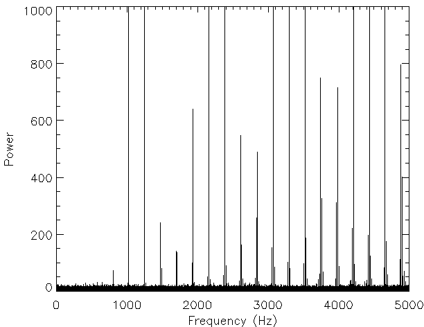
Figure. Power spectrum of BAT event data, showing spurious signals produced by round-off problems.
In fact, this problem can apply to any mission. For RXTE, the most commonly used high resolution timing mission, time-stamp values are always a multiple of a power of 2, which is exactly representable in a computer. Other instruments, with other quantizations, will have this problem as well, but typically do not have the right count rates to produce visible artifacts.
WORKAROUND: The problem basically arises because events fall almost on multiples of 100 microsecond, but not exactly. Assuming that one chooses time bins which are a multiple of 100 microseconds, a workaround to the problem is to add a small offset time to each event before performing timing analysis. Our experiments show that a 5 microsecond offset is sufficient to remove the artifacts. The science is totally unaffected, since the offset of 5 microseconds is twenty times smaller than the event time quantization.
Here is an example command that will add 5 microseconds to each of the event time stamps in a file called old.evt, and saves the result in a file called new.evt.
ftcopy old.evt'[col *; TIME=TIME+5e-6]' new.evt
After doing so, the artifacts vanish, as shown below.

Figure. BAT power spectrum after applying a 5 microsecond time offset. The spurious signals have vanished.
A more generic solution is to add a random number between 0 and 100 microseconds for each event, which allows any arbitrary time bin size.
The BAT team is working with the SDC in order to apply a workaround correction automatically.
Analysis: Passive materials distort the off-axis counts/rates
|
Task: |
All flux extraction (batfftimage/batmaskwtevt/batmaskwtimg/batbinevt) |
|
Version: |
All versions |
|
What builds: |
All builds |
|
Problem: |
Passive materials introduce errors in mask-weighted counts/rates |
|
Status: |
Corrective Procedure (HEASoft 6.0.3) |
|
Updated: |
15 Oct 2005 |
The BAT image system works by forming shadow patterns cast by the mask onto the detector array. The mask is made from lead tiles. However, the mask support structure also contains significant absorbing materials. The edge of the support structure is a particular problem because (a) extra absorbing materials (e.g. epoxy) were applied, and (b) this material rises up above the plane of the mask. The net result is that for sensitive imaging and spectroscopy of off-axis sources, the full mask aperture cannot be used.
The BAT team has provided a new set of aperture files in CALDB, tied to the HEASoft 6.0.3 release. These apertures have been reduced in size to appropriately block out the shadows of most of the absorbing material. However, this does reduce solid angle sky coverage by 5-10%.
The aperture files are now divided into two classes:
FLUX - reduced aperture for sensitive flux measurements (DEFAULT)
DETECTION - full aperture for largest solid angle and most illuminated detectors, but reduced flux accuracy
We should note that the differences between these apertures are small. The "old" DETECTION apertures can still be used if desired, but the FLUX apertures are likely to be what most users want, and are thus the default. The aperture type is selectable in the raytracing tasks using aperture=CALDB:FLUX or aperture=CALDB:DETECTION.
batfftimage and batmaskwtimg: potentially incorrect derived attitude
|
Task: |
Imaging tasks (batfftimage and batmaskwtimg) |
|
Version: |
All versions |
|
What Builds: |
All builds |
|
Problem: |
Attitude may be incorrect for observation with many snapshots |
|
Status: |
Corrective Procedure |
|
Updated: |
15 Oct 2005 |
Two imaging tasks assume that the spacecraft attitude is fixed during an observation: batfftimage (to make sky images) and batmaskwtimg (to make mask weighting maps for flux extraction). Both tasks take the time at the midpoint of the observation.
If there are gaps in the observation, i.e. multiple snapshots, then it is possible, even likely, that the midpoint time will fall within a gap. When this happens, the attitude may be erroneously interpolated.
The recommended solution is to use the 'batsurvey-aspect' to generate a new attitude file based on the median pointing direction. You will need to supply a good time interval extension, which should be available in any detector or sky images produced by BAT software. The 'batsurvey-aspect' command is:
batsurvey-aspect gtifile.gti swNNNNNNNNNNNsat.fits detimage.att
where swNNNNNNNNNNNsat.fits is the spacecraft attitude file, gtifile.gti is the good time interval you are interested in, and detimage.att is the new attitude file valid during that good time interval only. [ If you like, instead of gtifile.gti, you can use the good time interval attached to a detector image, such as 'snapshot.dpi[STDGTI]'. ] If you prefer, you can also use the plain 'aspect' task, but it is worth using 'batsurvey-aspect' sine it does some convenient error checking.
Updated (20 Oct 2008) - to recommend the batsurvey-aspect solution.
Updated (19 May 2005) - to recommend only the 'aspect' solution.
Updated (15 Oct 2005) - both batfftimage and batmaskwtimg now analyze the midpoint of the time interval
Analysis: Earth and Moon Occultation
|
Task: |
Flux extraction tasks (batmaskwtevt,batmaskwtimg,batfftimage) |
|
Version: |
All versions |
|
What Builds: |
All builds |
|
Problem: |
Earth and moon may block parts of the BAT field of view |
|
Status: |
Corrective procedure |
|
Updated: |
15 Oct 2005 |
The BAT field of view is large, approximately 120 x 60 degrees fully coded. The current spacecraft constraint excludes the sun with a 45 deg constraint cone, and the earth limb and moon with 30 degree constraints each.
Even so, the Earth and Moon may enter the BAT field of view. This will most commonly occur at edges of the "long" BAT axis (i.e. large IMX in the image plane). The effect will be to occult the flux of sources in that part of the sky. Since the Moon and (primarily) the Earth move as a function of time, the blockage may have the effect of reducing, but not totally eliminating the source on-time.
Example: in a 2000 second image, Sco X-1 might be blocked during the final 300 seconds.
The BAT team has released two tools to aid in correcting for occultation.
batoccultmap produces a fractional exposure map for a full sky image. Users provide the sky image and the prefilter attitude file ("SAO" file), and batoccultmap computes the fractional sky exposure in each pixel. This task should be used when users are interested many sources at one time.
NOTE: we suggest to only correct for earth occultation. Correcting for sun/moon occultation typically does not help, since it changes the image statistics in a non-smooth way.
batoccultgti produces a good time interval file (GTI file) for a known source. Good times are selected based on being unocculted and/or in a certain position in the field of view. This task should be used when users are interested in a particular source (i.e. not imaging), and should be used to filter the input data by time before further analysis.
Updated (15 Oct 2005) - to discuss the new occultation tasks
Old Issues
See this page for older issues.


